Process Is The Main Thing

@ Anatoly Belaychuk’s BPM Blog

Posts Tagged ‘BPMN’

Process Pattern: Post Office

In the previous post we considered a message from external entity that needs to be processed to determine which process instance it should be routed to. But at least there were no incertainity about which process template (process type) the message corresponds: client requests a credit card from a clerk (credit card issuance process),  CV arrives to Human Resources (enrollment process), payment notification reaches Finance (sales process).

Now let’s consider more complicated case: documents arrive to the company’s post address by traditional mail. They don’t reach process participant’s desk directly but go to the general administration office. » read the rest

07/07/11 | Articles | , ,     Comments: 12

Process Pattern: Incoming Processor

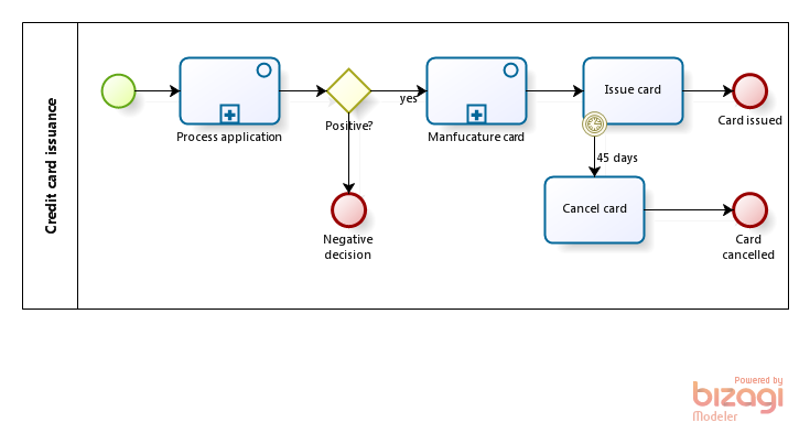
Let’s consider the credit card issuance process:

Fig. 1. Credit card issuance with a “passive” task “Issue card”.

Business scenario: after the card is manufactured, the client must come to the bank branch within 45 days and request it. Now look at the task “Issue card”: if the average client comes in for the card after 10 days and the branch issues 100 cards per day then 1000 of these tasks will queue into bank clerk’s task list. » read the rest

07/01/11 | Articles | ,     Comments: 63

Limited Usability of BPMN Lanes

Lanes (known as swimlanes in BPMN 1.x) represent process performers in BPMN.

Rules for the lanes:

  1. Lanes are optional.
  2. Lanes may be nested (hierarchical).
  3. Lanes semantics is fully at the discretion of the diagram’s author - it may be a function, role, position…
  4. Embedded subprocesses do not have pools and therefore can’t have lanes.
  5. Lanes are meaningful only to the user tasks - service tasks, script tasks, subprocesses, gateways, events are irrelevant to which lane you put them in.
  6. Even for the user tasks the lane is essentially a comment - actual performer is defined by the model attributes of the given task.

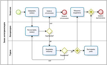
Novice BPMN users love lanes and use them at first excercises with enthusiasm:

Figure 1. BPMN diagram with lanes.

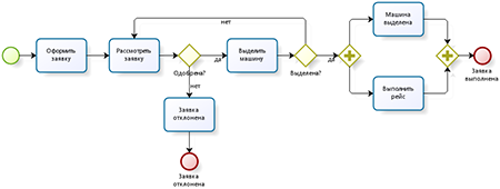
However using lanes won’t allow showing the process “happy path” which arguably is more valuable from ease of perception standpoint:

Figure 2. BPMN diagram with a happy path.

Moreover, when dealing with large processes there is no room for lanes at all.

There is a general rule applicable to any notation including BPMN: the number of activities at any diagram level should not exceed 7-9. Otherwise the scheme becomes too difficult to perceive:

Figure 3. “Flat” diagram with a large number of activities is hard to understand.

Accordingly, if the process comprises a large number of tasks, it should be decomposed into subprocesses:

Figure 4. Subprocesses help creating a simple diagram from a complex process.

But this style of modeling leaves no room for lanes:

  • At the top level there are only subprocesses while lanes apply only to the user tasks (rule 5).
  • Subprocess diagram doesn’t allow pools nor lanes (rule 4).

More precisely, rule 4 applies only to the embedded processes; reusable subprocesses may have lanes. I’ve seen diagrams where reusable subprocesses where used instead of embedded solely to be able to depict lanes. This is definitely bad practice - embedded subprocesses shall be used for the decomposition. Reusable subprocesses introduce additional complexity because unlike embedded they are executed in a separate data context.

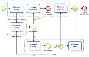
If you can’t live without diagramming performers then use BPMN artifact “group”:

Figure 5. BPMN groups shows performers within the embedded subprocess.

06/27/11 | Articles | ,     Comments: 32

Modeling Subprocesses in BPMN

If you’re working with on a complex enough business process then at some point the process diagram will become bloated and unreadable. This means it’s time to make hierarchical decomposition - in simple words, split the process to subprocesses. The old rule of having 5 to 9 activities per level is fully applicable to BPMN.

Let’s consider the contract process with three phases:

  1. Agree essential terms of the contract
  2. Agree the contract text
  3. Authorize the contract

Naive process diagrams like the following aren’t rare:

» read the rest

05/27/11 | Articles | , , ,     Comments: 22

BPMN Orchestration-Collaboration Balance

Definition 1: Orchestration - a diagram depicting a sequence of activities coordinated from a single center of control.

Notes:

  • Synonyms to orchestration are workflow and, in fact, process.
  • Orchestration is modeled by a white-box pool in BPMN; it may also contain optionally black-box pools presenting external entities.
  • The phrase “coordinated from a single center of control” means that even if a process diverges at some point, the branches remain coordinated e.g. they can be synchronized later in a converging fork; the whole process will end when all branches are completed.

Definition 2: Collaboration - a diagram showing interactions between processes.

Notes:

  • In BPMN 1.x interprocess communication was called choreography. In BPMN 2.0 choreography is reserved for a totally new type of diagram - what used to be a choreography in BPMN 1.x is called collaboration now. So it goes.
  • A collaboration diagram contains more than one white-box pool.
  • Some people reduce collaboration to the exchange of messages but generally speaking, processes may communicate via messages, signals and/or data (data store, conditional event).
  • Processes on a collaboration diagram are executed independently except specific sync points where messages and signals are sent/received, data read/written.

The big BPMN advantage is its support of collaboration as well as orchestration. This is also a key criterion for choosing a BPMS. Yet as my BPMN training shows, the right balance between orchestration and collaboration is tricky.

There are two common pitfalls:

  1. At a first approach to BPMN analysts try to do the job with orchestration only. Yet it works only for very simple processes like vacation request. Cross-functional processes that are of greatest interest for the business are multi-threaded by nature and hence can’t be modeled within orchestration.
  2. After getting acquainted with messages and learning that they can only be used between pools, many analysts introduce unnecessary pools into their diagrams. For example they love to use pools and messages where a subprocess would suffice:

Fig.1 Process antipattern: “Messaging instead of subprocess”

The common arguments in favor of this scheme:

  • “This process is performed by another entity.” - Use swimlanes not pools to show a performer.
  • “The process can be called from several points.” - So do reusable subprocesses.
  • “The link between the caller and the calling process becomes visible.” - First of all, expanded subprocesses are transparent, too:

Fig.2 Expanded subprocess

  • Secondly, for a well-structured diagram with properly separated abstraction levels collapsed subprocesses are sufficient: when we look at the process top-level, we must understand its logic without knowing the details of subprocesses. The subprocess contents shaill be presented on a separate page:

Fig.3 Collapsed subprocess

It’s a matter of style rather than correctness - the diagram in Figure 1 is formally correct. Yet I recon it’s an antipattern and inventing a wheel because messages are used to model a behaviour witch is already built-in into subprocess invocation:

  • when a control flow reaches a subprocess a token emerges with a subprocess and the caller goes into a wait state
  • when the subprocess completes the caller continues

In summary, here are my rules for the optimal balance between orchestration and collaboration:

Rule 1. If your attempts to model a process are unsuccessful because some significant aspects are missed repeatedly then stop and think - maybe in fact it’s not a single process but two or more?

Rule 2. Do not overuse collaboration - stay within the orchestration as long as possible. Never introduce collaboration into a diagram just because you’ve recently learned how to do that.

In the following article I’ll share my experience of identifying independent processes during analysis.

05/19/11 | Articles | , ,     Comments: 2

Inter-Process Communication Via Data Revisited

Ivo Velitchkov made me pay attention to the difference between BPMN 1.x и BPMN 2.0 in respect to data flow modeling.

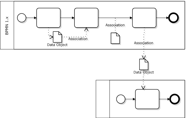
Data exchange in BPMN 1.x is modeled with Data Objects:

Fig. 1 Data Objects in BPMN 1.x

BPMN 1.x Data Object is an artifact used to inform what a process does. With the help of Association it may be linked to a Task, Control Flow or Message Flow yet it won’t directly affect any of them.

Data Objects can model a range of physical or electronic objects. We may for example drop a Data Object outside a pool and label it “Orders Database” in order to model interprocess communications via data.

Yet as Ivo rightfully pointed out the diagram depicted above becomes illegal under BPMN 2.0!

The point is that Data Object is associated with a process context in BPMN 2.0: it is drawn within a process (subprocess) boundary and it only exists from a process (subprocess) instance start to end. Therefore it can’t be accessed from the external process.

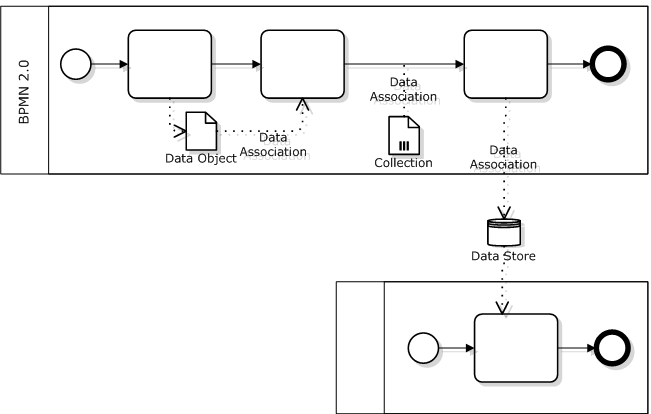
Persistent data not tied to a process lifecycle are modeled with Data Store, so this element should be used to model interprocess communication via data in BPMN 2.0:

Fig. 2. Data Objects and Data Stores in BPMN 2.0

As a side note, BPMN 2.0 makes a difference between single-item data objects and collections - the latter carry a special marker. It also introduces special markers for Data Inputs and Data Outputs and new elements - Input Sets and Output Sets.

BPMN 2.0 also defines Data Association in addition to the general Association inherited from 1.x. While general Association serves documenting purposes only, the Data Association is “executable”: one may define source, target and optionally transformation at the model attribute level. One may define right at the model the data manipulations that should be performed at activity start and end, message send and receive. Visual representation remains the same: dotted line with V-shaped arrow.

BPMN 2.0 specification is slightly controversial with respect to Data Association:

  • P.221 says that Data Association is used with Data Objects without mention of Data Stores. Since Data Objects always belong to a process, one may conclude that Data Associations should never cross a pool border. This rule would make the second diagram illegal - please refer to Ivo Velitchkov’s comment.
  • Yet p.208 says clearly that Data Store may serve as input or output for a Data Association.

So I believe that the diagram at fig.2 is valid.

Besides, even if you or your tool has objections against using Data Associations with Data Stores then you still can use plain old Associations that look exactly the same.

04/07/11 | Articles | ,     Comments: 3

Cross-Functional Patterns

It’s time to pay the debts - returning to cross-functional processes modeling as promised.

Remindment: the first part stated that it’s usually impossible to implement cross-functional processes by orchestration only (i.e. within a single BPMN pool). The borders betwen departments are material, they mark differences in manner and rhytm of different kinds of work. Because of these differences the fragments of a process belonging to each department are technically implemented by separate pools while the cross-functional process as a whole is implemented by a set of such pools communicating via messages and data.

In this article we’ll consider common cross-functional process patterns.

Let’s use the following example:

Under routine financial planning all bills received by a company are processed by the finance department first: they determine validity of the claim, check the amount and date, assign priority in accordance with established business rules. Then the bill is submitted for approval to CFO or some other manager who makes a decision about payment taking into account priority, amount and term.

The simplest process diagram may look like this:

» read the rest

02/09/11 | Articles | , ,     Comments: 19

BPMN In Outer Space

My friend deals with telecom processes. There is a specificity that I covered before: a lot of coordination between systems and relatively little human participation.

Anyway, he was interested in BPMN and wanted to assess it with a test case. Here is the case as I’ve got it; if you found it incomplete or contradictory, that’s fine and normal for a real-world cases.

A case based on the Star Wars: two space cruisers are on alert to repel a possible aliens attack.

a) Ship paths are plotted centrally and synchronized on the basis of data obtained in real time, aiming at maximum security and full dangerous zones coverage.

b) The appearance of an alien object on the radar is recorded and replicated to the mate ship’s tracking system - this way each target receives its own individual id. When it’s lost by both ships the target obtains lost status - there is no means to differentiate a new target from a target that once has been tracked and then lost.

c) The system that assigns targets to one cruiser or another is centralized and works on the basis of priorities (no matter which ones). The system may transfer a target from one cruiser to another if priorities have changed - that is, each target is marked with 1 or 2, indicating to whom it is assigned at any given time.

d) A command to open fire is displayed on a touch screen display and the operator makes a decision by pressing the button. Even at this moment the system may reassign the target to another cruiser.

e) If the target is hit then the workflow ends, otherwise the failed attempt is logged and the process continues. It’s assumed for simplicity that the laser weapon is used and the outcome of a shot is determine promptly enough.

It’s assumed that the whole process runs continuously.

Rather unusual domain for BPMN, right? So the questions arise:

  • Can the task be solved with a help of BPMN?
  • Is it worth it?
  • Well, the solution itself, if any.

Hope you found the case interesting; I was intrigued.

My version of the BPMN diagram (click to open in a new window):

» read the rest

12/29/10 | Articles |     Comments: 8

Modeling Human Routing in BPMN

Unfortunately, the question “how to model human decisions in BPMN” isn’t frequently asked.

“Unfortunately” because the intuitive answer is wrong. This is not a fork but a parallel execution:
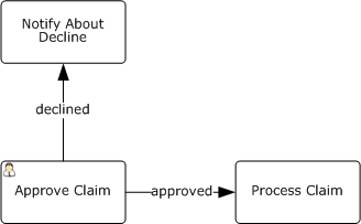
After exiting the “Approve Claim” task the process will continue in parallel on the outgoing flows whatever is written on them.

Valid BPMN diagram looks like this:
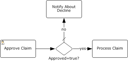
It’s implied that the process has a boolean attribute “Approved”. User sets this attribute at the “Approve Claim” task, the gateway checks its value and the process continues in one of the flows.

As you can see, BPMN authors didn’t provide a special construct for human decisions but implemented them rather artificially: a special attribute that must be set by a human and checked in the gateway immediately after.

The user interface for the task where the decision is made may look like this:

When “Done” button form is pressed the task is completed.

I agree with Keith Swenson that BPMN misses explicit support of human routings.

Firstly, human-based and automatic routings look alike at a diagram. Yet this is an important aspect of the process.

If it was my decision I’d introduce explicit support of human routing into BPMN. Since first diagram above is actually more intuitive than valid BPMN, I’d leverage on it:
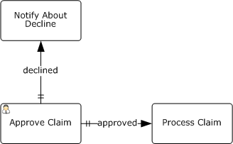
The existing flow types - Control Flow, Conditional Flow and Uncontrolled Flow - are extended by Human Controlled Flow here, marked with a double dash.

Another issue are screen forms like the one above which provoke user mistakes: it’s tempting to press “Done” and get rid of the task without paying attention to the attributes.

If a decision is requested from a human then the form should look like this:

The buttons could be generated automatically from the process diagram above.

Yet it’s possible to utilize this technique for standard BPMN, too:
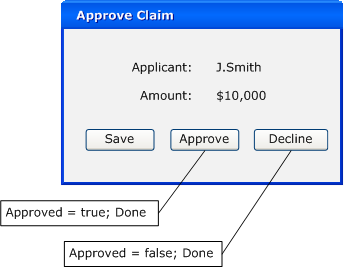
“Done” button is replaced by “Approve” and “Deny” here, each of them being bound to two actions: set the attribute value and complete the task.

Now I’m going to use this occasion to appeal to BPMS vendors: please give the opportunity to create more than one button completing the task and bind them to attributes. If you didn’t do it yet, of course.

12/27/10 | Articles | , , ,     Comments: 12

(Русский) Несколько образчиков годного BPMN

Sorry, this entry is only available in Русский.

12/14/10 | News | ,     Comments: closed

Copyright © 2008-2024 Anatoly Belychook. Thanks to Wordpress and Yahoo.  Content  Comments