Process Is The Main Thing

@ Anatoly Belaychuk’s BPM Blog

Posts Tagged ‘pattern’

Modeling Subprocesses in BPMN

If you’re working with on a complex enough business process then at some point the process diagram will become bloated and unreadable. This means it’s time to make hierarchical decomposition - in simple words, split the process to subprocesses. The old rule of having 5 to 9 activities per level is fully applicable to BPMN.

Let’s consider the contract process with three phases:

  1. Agree essential terms of the contract
  2. Agree the contract text
  3. Authorize the contract

Naive process diagrams like the following aren’t rare:

» read the rest

05/27/11 | Articles | , , ,     Comments: 22

BPMN Orchestration-Collaboration Balance

Definition 1: Orchestration - a diagram depicting a sequence of activities coordinated from a single center of control.

Notes:

  • Synonyms to orchestration are workflow and, in fact, process.
  • Orchestration is modeled by a white-box pool in BPMN; it may also contain optionally black-box pools presenting external entities.
  • The phrase “coordinated from a single center of control” means that even if a process diverges at some point, the branches remain coordinated e.g. they can be synchronized later in a converging fork; the whole process will end when all branches are completed.

Definition 2: Collaboration - a diagram showing interactions between processes.

Notes:

  • In BPMN 1.x interprocess communication was called choreography. In BPMN 2.0 choreography is reserved for a totally new type of diagram - what used to be a choreography in BPMN 1.x is called collaboration now. So it goes.
  • A collaboration diagram contains more than one white-box pool.
  • Some people reduce collaboration to the exchange of messages but generally speaking, processes may communicate via messages, signals and/or data (data store, conditional event).
  • Processes on a collaboration diagram are executed independently except specific sync points where messages and signals are sent/received, data read/written.

The big BPMN advantage is its support of collaboration as well as orchestration. This is also a key criterion for choosing a BPMS. Yet as my BPMN training shows, the right balance between orchestration and collaboration is tricky.

There are two common pitfalls:

  1. At a first approach to BPMN analysts try to do the job with orchestration only. Yet it works only for very simple processes like vacation request. Cross-functional processes that are of greatest interest for the business are multi-threaded by nature and hence can’t be modeled within orchestration.
  2. After getting acquainted with messages and learning that they can only be used between pools, many analysts introduce unnecessary pools into their diagrams. For example they love to use pools and messages where a subprocess would suffice:

Fig.1 Process antipattern: “Messaging instead of subprocess”

The common arguments in favor of this scheme:

  • “This process is performed by another entity.” - Use swimlanes not pools to show a performer.
  • “The process can be called from several points.” - So do reusable subprocesses.
  • “The link between the caller and the calling process becomes visible.” - First of all, expanded subprocesses are transparent, too:

Fig.2 Expanded subprocess

  • Secondly, for a well-structured diagram with properly separated abstraction levels collapsed subprocesses are sufficient: when we look at the process top-level, we must understand its logic without knowing the details of subprocesses. The subprocess contents shaill be presented on a separate page:

Fig.3 Collapsed subprocess

It’s a matter of style rather than correctness - the diagram in Figure 1 is formally correct. Yet I recon it’s an antipattern and inventing a wheel because messages are used to model a behaviour witch is already built-in into subprocess invocation:

  • when a control flow reaches a subprocess a token emerges with a subprocess and the caller goes into a wait state
  • when the subprocess completes the caller continues

In summary, here are my rules for the optimal balance between orchestration and collaboration:

Rule 1. If your attempts to model a process are unsuccessful because some significant aspects are missed repeatedly then stop and think - maybe in fact it’s not a single process but two or more?

Rule 2. Do not overuse collaboration - stay within the orchestration as long as possible. Never introduce collaboration into a diagram just because you’ve recently learned how to do that.

In the following article I’ll share my experience of identifying independent processes during analysis.

05/19/11 | Articles | , ,     Comments: 2

Inter-Process Communication Via Data Revisited

Ivo Velitchkov made me pay attention to the difference between BPMN 1.x и BPMN 2.0 in respect to data flow modeling.

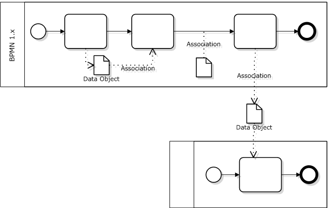
Data exchange in BPMN 1.x is modeled with Data Objects:

Fig. 1 Data Objects in BPMN 1.x

BPMN 1.x Data Object is an artifact used to inform what a process does. With the help of Association it may be linked to a Task, Control Flow or Message Flow yet it won’t directly affect any of them.

Data Objects can model a range of physical or electronic objects. We may for example drop a Data Object outside a pool and label it “Orders Database” in order to model interprocess communications via data.

Yet as Ivo rightfully pointed out the diagram depicted above becomes illegal under BPMN 2.0!

The point is that Data Object is associated with a process context in BPMN 2.0: it is drawn within a process (subprocess) boundary and it only exists from a process (subprocess) instance start to end. Therefore it can’t be accessed from the external process.

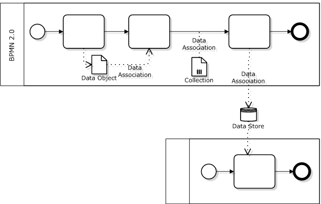
Persistent data not tied to a process lifecycle are modeled with Data Store, so this element should be used to model interprocess communication via data in BPMN 2.0:

Fig. 2. Data Objects and Data Stores in BPMN 2.0

As a side note, BPMN 2.0 makes a difference between single-item data objects and collections - the latter carry a special marker. It also introduces special markers for Data Inputs and Data Outputs and new elements - Input Sets and Output Sets.

BPMN 2.0 also defines Data Association in addition to the general Association inherited from 1.x. While general Association serves documenting purposes only, the Data Association is “executable”: one may define source, target and optionally transformation at the model attribute level. One may define right at the model the data manipulations that should be performed at activity start and end, message send and receive. Visual representation remains the same: dotted line with V-shaped arrow.

BPMN 2.0 specification is slightly controversial with respect to Data Association:

  • P.221 says that Data Association is used with Data Objects without mention of Data Stores. Since Data Objects always belong to a process, one may conclude that Data Associations should never cross a pool border. This rule would make the second diagram illegal - please refer to Ivo Velitchkov’s comment.
  • Yet p.208 says clearly that Data Store may serve as input or output for a Data Association.

So I believe that the diagram at fig.2 is valid.

Besides, even if you or your tool has objections against using Data Associations with Data Stores then you still can use plain old Associations that look exactly the same.

04/07/11 | Articles | ,     Comments: 3

Cross-Functional Process Optimization

This is third and last part of a study on managing cross-functional business process. Previous parts:

  1. Vulgar Interpretation of Cross-Functional Business Processes
  2. Cross-Functional Patterns

In the second part we introduced two basic ways to organize work within cross-functional business processes:

  • Synchronous - the performing unit starts work as soon as it received an internal order. Technically it’s implemented by a single process.
  • Asynchronous - orders are first accumulated in the input buffer unit of the performing unit, then extracted and processed with some frequency. Technically it’s implemented by two (when there is a single resource) or larger number of processes.

Synchronous mode grants minimal process execution time while asynchronous maximizes the performance (measured by the number of process instances completed per unit of time).

According to my observations asynchronous mode prevails in real life because departments and people both feel more comfortable when they are not chased by a continuous flow of a variety of tasks but have an opportunity to somehow organize and plan their activities.

Business and process analysts prefer synchronous schemes - not with something special in mind but because they just follow the path of least resistance: these schemes are plain simpler. This may lead to conflicts at the process implementation: people are pushed into the process framework which they feel uncomfortable.

Now if we look at it from the organization’s goals perspective (i.e. process performance) then the synchronous scheme is preferred because it provides the highest quality of customer service. A performer may not feel comfortable but it doesn’t matter on the condition that he/she isn’t overloaded (which does not happen as often as it may seem). Improving an individual’s performance may be a sub-optimization which is a bad word.

How can we bring these views together? I’m going to give some recommendation about optimal process schemes

» read the rest

02/17/11 | Articles | ,     Comments: 8

Cross-Functional Patterns

It’s time to pay the debts - returning to cross-functional processes modeling as promised.

Remindment: the first part stated that it’s usually impossible to implement cross-functional processes by orchestration only (i.e. within a single BPMN pool). The borders betwen departments are material, they mark differences in manner and rhytm of different kinds of work. Because of these differences the fragments of a process belonging to each department are technically implemented by separate pools while the cross-functional process as a whole is implemented by a set of such pools communicating via messages and data.

In this article we’ll consider common cross-functional process patterns.

Let’s use the following example:

Under routine financial planning all bills received by a company are processed by the finance department first: they determine validity of the claim, check the amount and date, assign priority in accordance with established business rules. Then the bill is submitted for approval to CFO or some other manager who makes a decision about payment taking into account priority, amount and term.

The simplest process diagram may look like this:

» read the rest

02/09/11 | Articles | , ,     Comments: 19

Modeling Human Routing in BPMN

Unfortunately, the question “how to model human decisions in BPMN” isn’t frequently asked.

“Unfortunately” because the intuitive answer is wrong. This is not a fork but a parallel execution:
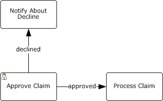
After exiting the “Approve Claim” task the process will continue in parallel on the outgoing flows whatever is written on them.

Valid BPMN diagram looks like this:
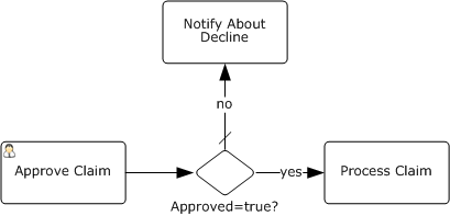
It’s implied that the process has a boolean attribute “Approved”. User sets this attribute at the “Approve Claim” task, the gateway checks its value and the process continues in one of the flows.

As you can see, BPMN authors didn’t provide a special construct for human decisions but implemented them rather artificially: a special attribute that must be set by a human and checked in the gateway immediately after.

The user interface for the task where the decision is made may look like this:

When “Done” button form is pressed the task is completed.

I agree with Keith Swenson that BPMN misses explicit support of human routings.

Firstly, human-based and automatic routings look alike at a diagram. Yet this is an important aspect of the process.

If it was my decision I’d introduce explicit support of human routing into BPMN. Since first diagram above is actually more intuitive than valid BPMN, I’d leverage on it:
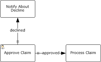
The existing flow types - Control Flow, Conditional Flow and Uncontrolled Flow - are extended by Human Controlled Flow here, marked with a double dash.

Another issue are screen forms like the one above which provoke user mistakes: it’s tempting to press “Done” and get rid of the task without paying attention to the attributes.

If a decision is requested from a human then the form should look like this:

The buttons could be generated automatically from the process diagram above.

Yet it’s possible to utilize this technique for standard BPMN, too:
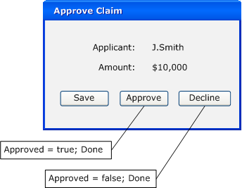
“Done” button is replaced by “Approve” and “Deny” here, each of them being bound to two actions: set the attribute value and complete the task.

Now I’m going to use this occasion to appeal to BPMS vendors: please give the opportunity to create more than one button completing the task and bind them to attributes. If you didn’t do it yet, of course.

12/27/10 | Articles | , , ,     Comments: 12

(Русский) Несколько образчиков годного BPMN

Sorry, this entry is only available in Русский.

12/14/10 | News | ,     Comments: closed

Interprocess Communications Via Data

Here is a test for my readers.

Question: What BPMN elements may be used to model interprocess communications (mark all correct options) -

  1. sequence flow
  2. message flow
  3. signal event
  4. conditional event
  5. association

Answer: click to see the answer

Comments to the answer:

» read the rest

11/12/10 | Articles | , , ,     Comments: 9

Warning About BPMN Signal Event

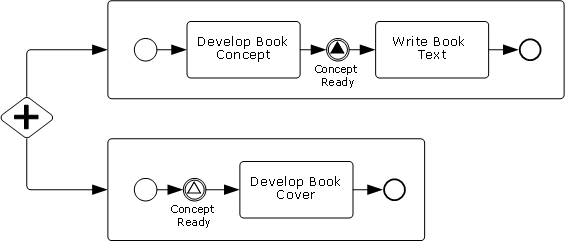
Let’s consider a process diagram borrowed (with some simplifications) from the book by Stephen White, Derek Miers, “BPMN Modeling And Reference Guide”, p. 113:

The diagram illustrates a fragment of book creation process. The process splits into two subprocesses executed in parallel: writing text and developing book cover. The point is that book cover development may start only when the concept is ready.

The challenge of implementing this logic is that we can’t use sequence flow because it cannot cross subprocess boundary. (Let’s leave apart the question why we need subporcesses here; let’s just suppose we need them for some reason.) We can’t use message flow either because it’s all within a single pool.

The standard recommendation is to use BPMN signal event:

  • when the concept is ready, first subporcess triggers a signal
  • second process was awaiting for the signal; after catching the signal it proceeds to “Develop Book Cover” task

It’s so called “Milestone” process pattern. A similar example of BPMN signal usage is given in the book by Bruce Silver, “BPMN Method and Style”, p. 98.

Where is the catch?

Everything is OK as long as we consider a signle book creation. Now let’s suppose several books are processed at once. Recalling that BPMN signal is broadcasted to everyone awaiting it at the given moment, as soon as the concept of first book is ready all designers will receive the signal to start developing the cover. Not exactly what we expected.

In order to make the diagram work we must limit the signal propagation somehow. How it can be done?

  1. The first thing that comes into my mind is an attribute that would limit signal broadcasting by the current process instance boundaries. Yet there is no such attribute in the standard. Under BPMN 1.x one may say that it’s implementation issue not covered by the standard. But BPMN 2.0 fully specify the process metamodel. Let’s look at page 281 of OMG document dated June 2010: signal has a single attribute - its name. Therefore, a signal will be transmitted to all process instances.
  2. If the signal has only name then let’s use what we have. The diagram above may work if we could change signal name dynamically i.e. during the process execution. If we could name the signal “Process 999 Concept Ready” instead of “Concept Ready” then everything will be fine. But it’s a dirty hack and it’s hard to count on it. BPMS engines allow to change certain things during the execution (e.g. timer settings) but unlikely the name.

Why we should care.

Depending on whether we may use signal events to coordinate flows within a process instance, we should chose one process architecture or another:

  • if signals propagation can be limited, one can freely use subprocesses - whenever the need to synchronize them arises, it can be done by a signal
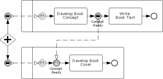
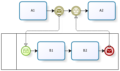
  • if signals transmit without limits then the only option is to launch separate processes for each branch because we can synchronize processes by message flows, resulting in a diagram like this:

Conclusions:

  1. The BPMN standard lacks an attribute giving an option to limit signal event propagation.
  2. As long as there is no way to limit the signal propagation, the “Milestone” process pattern should be implmented by message flows between separate pools.
11/05/10 | Articles | , , ,     Comments: 7

Process Pattern: Do-Redo

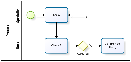
Very common case: an employee performs the task, his boss checks the work and may return it back for correction. It’s usually modelled like this:

BPMN process pattern: Do

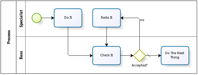
I recommend slightly more sophisticated diagram:

BPMN process pattern: Redo

The content of two jobs “Do” and “Redo” may not differ at all, it’s about task names. Now what’s the point:

  • Within the first scheme an employee sees a task in his list: “Do It. He does, then presses the button and… after 15 minutes he sees the same task belonging to the same process instance. It’s confusing, especially if he managed to work on some other things during these 15 (or 30, or 130) minutes.
  • The second diagram is also better from monitoring perspective: it’s easy to calculate the number of “Redo” executions and the total time spent for them and then focus on bringing them to zero. OK, the number of redo’s can be calculated within the first scheme too - by subtracting the number of process instances from the number of task executions. Yet the total time spent (i.e. unjustified costs) won’t be so easy to calculate within the first scheme.

So that’s the pattern: almost trivial yet (or therefore?) widely applicable.

10/12/10 | Articles | , ,     Comments: 11

Copyright © 2008-2024 Anatoly Belychook. Thanks to Wordpress and Yahoo.  Content  Comments